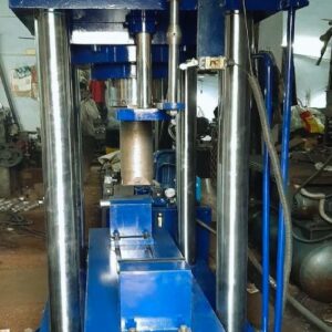
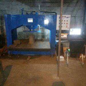
The EP (Electronic pneumatic) Unit Brake Controller and Modulator Test Bench are used to calibrate and test electronic pneumatic brakes found in different vehicles such as trains, trucks, and buses. This is a detailed breakdown of the features, technical specs, and operation cycle.
Features and Specifications of the EP Unit Brake Modulator Test Bench:
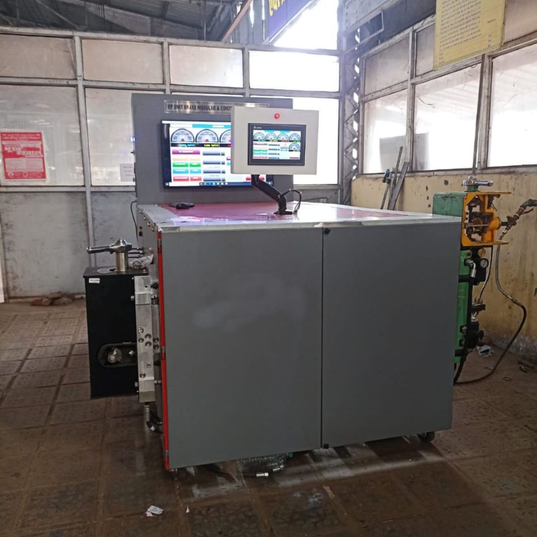
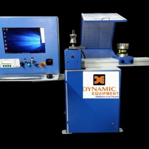
- Electronic Pneumatic Test Bench: This test bench was specifically designed to simulate the performance and evaluate the performance of electronic pneumatic brake modulators, controllers, and modern braking systems.
- Versatility This tester can test a variety of EP brakes including modulators and controllers as well as solenoid valves. It also tests pressure sensors.
- Realistic Simulation: This test bench simulates realistic braking scenarios including emergency braking and anti-lock braking (ABS) activation. It also includes traction control and electronic stability control.
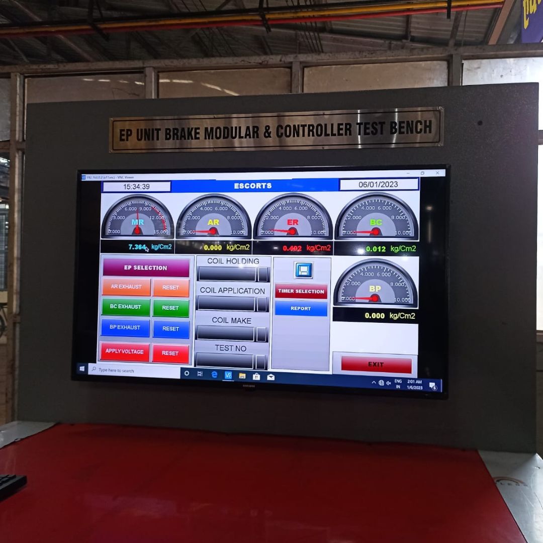
- Control & Monitoring: Allows precise control and monitoring of brake parameters, such as pressure and temperature, modulation frequencies, duty cycles, and response times.
- Data Acquiring: Modern test benches are equipped with data acquisition systems that capture and record data for analysis, such as pressure curves and valve response times.
- Safety Features: These devices are equipped with safety features such as emergency stop buttons and overpressure protection. They also have safety enclosures that ensure the safety of operators during test operations.
Technical Specifications for EP Unit Brake Modulator Test Bench:
- Pressure range: specifies the range of pneumatic persuasions that the test bench is capable of generating and controlling for testing purposes.
- Temperature control: Indicates a temperature range within which the test bench is capable of operating reliably. This ensures accurate simulation of actual conditions.
- Valve control: Specifies the number of solenoid valves and their control parameters including voltage, current, and pulse width modulation frequency (PWM).
- Accuracy Defines accuracy in pressure measurement, temperature control, and valve actuation. Typically expressed as a percent of full-scale or absolute units.
- Conformity: Ensures the test bench complies with relevant industry standards, such as SAE J1708 or J1939 for electronic pneumatic braking systems.
- Power Requirements Indicates electrical power requirements for the test bench including voltage, frequency, and power consumption.
Description:
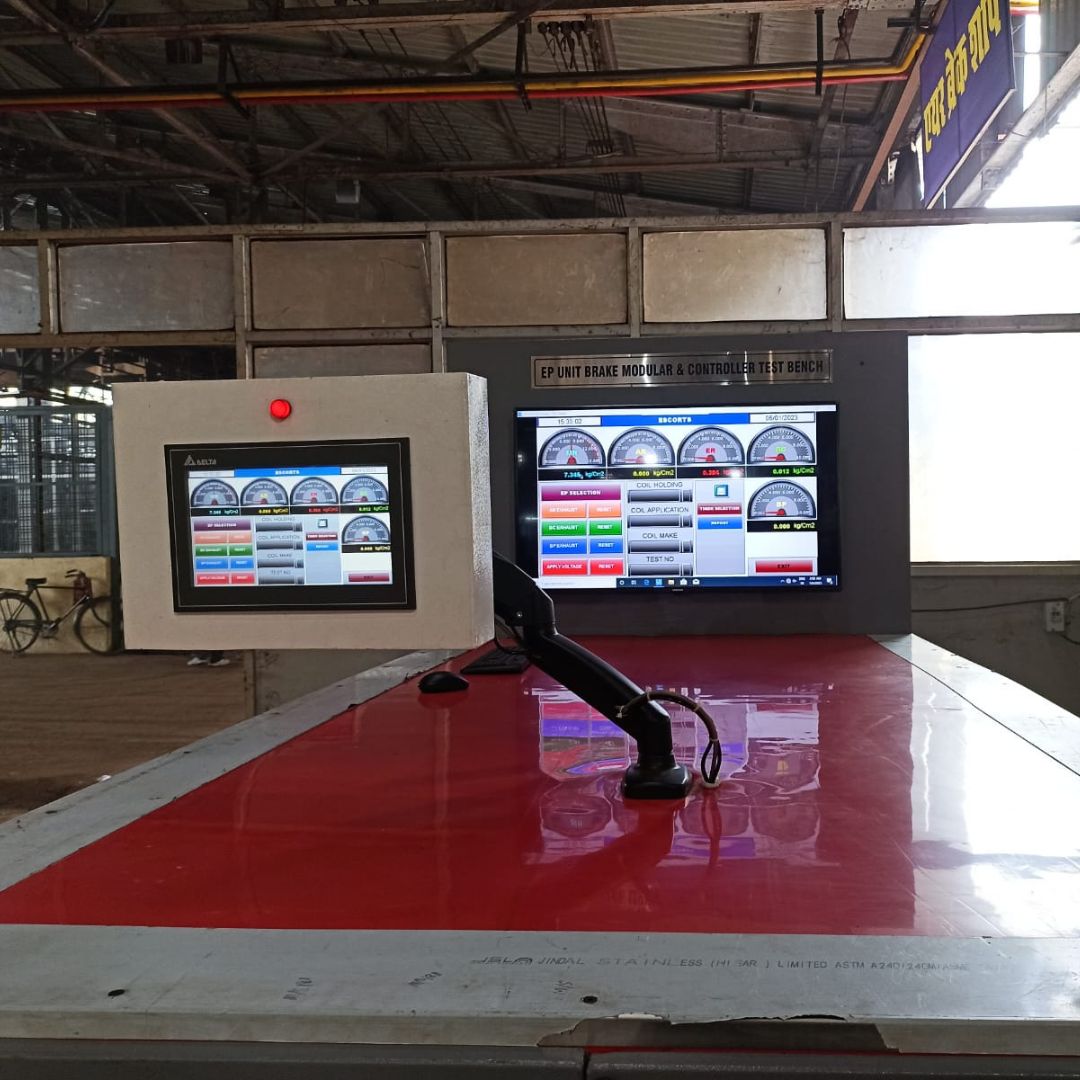
- Preparation The EP unit to be tested must be securely connected to the testing bench. This includes ensuring that pneumatic and electric connections are correct.
- Setup Test parameter settings are configured via the control panel of the test bench or software interface.
- Testing Phase The test bench simulates normal and emergency brake conditions, while monitoring key parameters.
- Data Acquiring: During the testing, data like pressure curves and valve response times are recorded and analyzed.
- Analysis Tests are analyzed to determine the EP brake’s performance, responsiveness, and reliability. Any issues or abnormalities identified will be investigated further.
- Reporting A comprehensive report is generated that documents the test procedure, test results, analysis, and any relevant observations for calibration or maintenance.


Reviews
There are no reviews yet.